| •
|
Thoroughly clean all parts to assembled.
|
| •
|
Before installing the parts, apply fresh engine oil to
all sliding and rotating surfaces.
|
| •
|
Replace all gaskets, O-rings and oil seals with new parts.
|
|
|
1. |
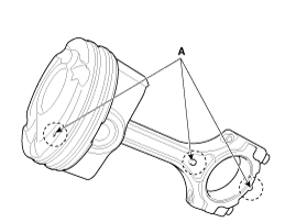
Assemble the piston and the connecting rod.
|
(1) |
Use a hydraulic press for installation.
|
|
(2) |
The piston front mark (A) and the connecting rod front
mark (A) must face the timing chain side of the engine.
Pressing load :
500 ~ 1,500 kg (1,102 ~ 3,306 lb)
|
|
|
|
2. |
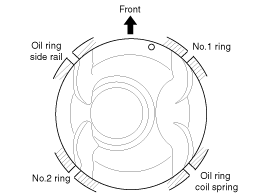
Assemble the piston rings.
|
(1) |
Install the oil ring coil spring and two side rails by
hand.
|
|
(2) |
Using a piston ring expander, install the 2 compression
rings with the code mark facing upward.
|
|
(3) |
Position the piston rings so that the ring ends are as
shown.
|
|
|
3. |
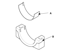
Assemble the connecting rod bearings.
|
(1) |
Align the bearing (A) claw with the groove of the connecting
rod and cap (B).
|
|
(2) |
Install the bearings (A) in the connecting rod and cap
(B).
|
|
|
4. |
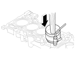
Insert the piston and connecting rod assemblies into the cylinder
bores.
|
Before installing the piston, apply a sufficient amount
of engine oil to the ring grooves and cylinder bores.
|
|
(1) |
Press the piston rings with a ring compressor and check
that the rings are securely in place. Then insert the piston
into the cylinder bore, and tap it in using the wooden handle
of a hammer.
|
|
(2) |
Stop after the ring compressor pops free, and check the
connecting rod-to-crank journal alignment before pushing the
piston into place.
|
|
(3) |
Install the rod caps with bearings, and tighten the bolts.
Tightening torque :
17.7 ~ 21.8 N.m (1.8 ~ 2.2 kgf.m, 13.0 ~ 15.9
lb-ft) + 88 ~ 92°
|
|
Always use new connecting rod cap bolts. Connecting
rod cap bolts are toque-to-yield bolts designed to be
permanently elongated beyond the state of elasticity
when torqued, so if the bolts are removed and reused,
it may cause the bolts to break or fail to maintain
clamping force.
|
|
|
|
5. |
Check the side clearance between piston and connecting rod.
|
|
6. |
Install the ladder frame.
|
(1) |
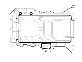
Apply the liquid gasket on the ladder frame.
Bead width :
2.5 ~ 3.5 mm (0.0984 ~ 0.1378 in)
|
|
• |
Apply the sealant, THREE-BOND 1217H or
LOCTITE 5900H on the ladder frame rail portion
and install it within five minutes. If sealant
is applied to cylinder block bottom position,
the sealant position should be the same as that
of the ladder frame rail.
|
|
• |
Apply sealant along the inner line of
the bolt holes.
|
|
|
|
(2) |
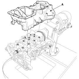
Install the ladder frame (A).
Tightening torque :
18.6 ~ 23.5 N.m (1.9 ~ 2.4 kgf.m, 13.7 ~ 17.4
lb-ft)
|
|
|
|
7. |
Assemble the other parts in the reverse order of disassembly.
|
Connecting Rod
1.
Check the side clearance between piston and connecting rod.
Using filler gauge, measure the side clearance while moving the
connecting rod bac ...
1. Crankshaft sprocket s
2. Crankshaft thrust bearing
3. Crankshaft upper main bearing
4. Crankshaft
5. CKPS wheel
6. Crankshaft lower main bearing
7. Crankshaft ma ...
See also:
Calendar Settings
This menu is used to set the date (MM/DD/YYYY).
Select [Calendar Settings]
Set through
TUNE knob
Press
TUNE knob
❈ Adjust the number currently in focus to make the s ...
Auto Head Lamp Leveling Unit Description
According to driving environment and loading state of vehicle, head
lamp lighting direction is changed to keep the driver's visibility range
and to protect the driver's vision from ...
Underdrive Brake Control Solenoid Valve(UD/B_VFS). Inspection
1.
Turn ignition switch OFF.
2.
Disconnect the solenoid valve connector (A).
3.
Measure resistance bet ...
 Kia Soul: Piston and Connecting Rod Reassembly
 Piston and Connecting Rod Inspection
 Crankshaft Components


