Signal Circuit Inspection
|
1. |
Check ignition lock switch pull-up voltage
|
(1) |
IG KEY "OFF", ENGINE "OFF".
|
|
(2) |
Disconnect ignition lock switch connector.
|
|
(4) |
Measure the voltage between signal terminal of ignition
lock switch harness connector and chassis ground.
Specification :
11.5V ~ 13.0V
|
|
|
|
2. |
Check open in ignition lock switch signal circuit
|
(1) |
IG KEY "OFF", ENGINE "OFF".
|
|
(2) |
Disconnect ignition lock switch connector and ECM connector.
|
|
(3) |
Check continuity between signal terminal of ignition lock
switch signal harness connector and ECM harness connector.
Specification :
Continuity ( below 1.0Ω )
|
|
|
Ground Circuit inspection
|
1. |
IG KEY "OFF", ENGINE "OFF".
|
|
2. |
Disconnect ignition lock switch connector.
|
|
3. |
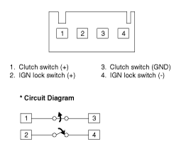
Check continuity between ignition lock switch signal harness connector
terminal 4 and chassis ground.
Specification :
Continuity ( below 1.0Ω )
|
|
Component Inspection
|
1. |
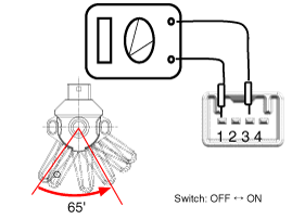
Remove the clutch & ignition lock switch.
|
|
2. |
Rotate the Ignition lock switch lever to the direction of the
arrow to check the continuity.

Clutch pedal position
|
Ignition lock switch
|
Released
|
Open
|
Fully pressed
|
Continuity
|

|
1.
Turn ignition switch OFF and disconnect the negative (-) battery
cable.
2.
Disconnect the ignition lock switch connector (A).
...
 Kia Soul: Inspection
 maincat
 Removal

