 Kia Soul: Purge Control Solenoid Valve (PCSV). Repair procedures
Kia Soul 2014-2019 PS Service Manual / Engine Control / Fuel System / Engine Control System / Purge Control Solenoid Valve (PCSV). Repair procedures
Inspection
| 1. |
Turn the ignition switch OFF.
|
| 2. |
Disconnect the PCSV connector.
|
| 3. |
Measure resistance between the PCSV terminals 1 and 2.
|
| 4. |
Check that the resistance is within the specification.
|
Removal
| 1. |
Turn the ignition switch OFF and disconnect the battery negative
(-) cable.
|
| 2. |
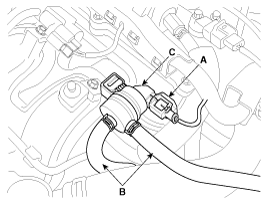
Disconnect the purge control solenoid valve connector (A).
|
| 3. |
Disconnect the vapor hoses (B) from the purge control solenoid
valve.
|
| 4. |
Remove the purge control solenoid valve (C).
|
Installation
|
|
| 1. |
Install in the reverse order of removal.
|
 Purge Control Solenoid Valve (PCSV). Schematic Diagrams
Circuit Diagram
(M/T)
(A/T)
...
 CVVT Oil Control Valve (OCV). Description and Operation
Description
Continuous Variable Valve Timing (CVVT) system advances or retards the
valve timing of the intake and exhaust valve in accordance with the ECM control
signal which is calculated ...
See also:
Knock Sensor (KS). Schematic Diagrams
Circuit Diagram
(M/T)
(A/T)
...
Instrument Cluster Control
Adjusting Instrument Cluster Illumination
The brightness of the instrument panel illumination is changed by pressing the
illumination control button ("+" or "-") when the ig ...
Coolant Replacement And Air Bleeding
Never remove the radiator cap when the engine is hot. Serious
scalding could be caused by hot fluid under high pressure ...


