 Kia Soul: Heater Unit Replacement
Kia Soul 2014-2019 PS Service Manual / Heating,Ventilation And Air Conditioning / Heater / Heater Unit Replacement
| 1. |
Disconnect the negative (-) battery terminal.
|
| 2. |
Recover the refrigerant with a recovery/recycling/charging station.
|
| 3. |
When the engine is cool, drain the engine coolant from the radiator.
(Refer to Engine Mechanical System - “Coolant”)
|
| 4. |
Remove the cowl top cover.
(Refer to Body - "Cowl Top Cover")
|
| 5. |
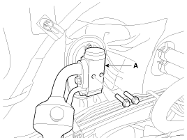
Remove the bolts and the expansion valve (A) from the evaporator
core.
|
| 6. |
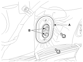
Remove the expansion valve flange (A) after loosening the screws.
|
| 7. |
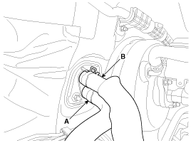
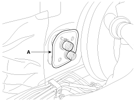
Disconnect the inlet (A) and outlet (B) heater hoses from the
heater unit.
|
| 8. |
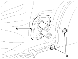
Remove the inlet and outlet heater hoses flange (A) after loosening
the nuts (B).
|
| 9. |
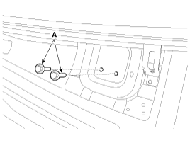
Loosen the cowl cross member mounting bolts (A).
|
| 10. |
Remove both sides of front seat assembly.
(Refer to Body - "Front Seat Assembly")
|
| 11. |
Remove the floor console assembly.
(Refer to Body - "Floor Console Assembly")
|
| 12. |
Remove the center fascia panel.
(Refer to Body - "Center Fascia Panel")
|
| 13. |
Remove the crash pad lower panel.
(Refer to Body - "Crash Pad Lower Panel")
|
| 14. |
Remove the glove box housing.
(Refer to Body - "Glove Box Housing")
|
| 15. |
Remove the crash pad center lower panel.
(Refer to Body - "Crash Pad Center Panel")
|
| 16. |
Remove both sides of the front pillar trim.
(Refer to Body - "Front Pillar Trim")
|
| 17. |
Remove both sides of the cowl side trim.
(Refer to Body - "Cowl Side Trim")
|
| 18. |
Remove the steering column shroud lower panel.
(Refer to Body - "Steering Column Shroud Panel")
|
| 19. |
Remove the steering wheel.
(Refer to Steering System - "Steering Wheel")
|
| 20. |
Remove the multifunction switch.
(Refer to Body Electrical System - "Multifunction Switch")
|
| 21. |
Lower the steering column after loosening the mounting bolts.
(Refer to Steering System - "Steering Column and Shaft")
|
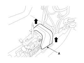
| 22. |
Remove the rear airduct assembly (A).
|
| 23. |
Remove the shift lever assembly.
(Refer to Automatic Transaxle System - "Shift lever")
|
| 24. |
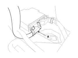
Disconnect the airbag control module (SRSCM) connector (A).
|
| 25. |
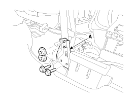
After loosening the mounting bolts and nuts, then remove the cowl
cross bar center bracket (A).
|
| 26. |
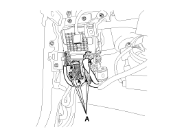
Disconnect the passenger compartment junction box connectors (A).
|
| 27. |
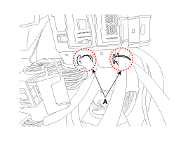
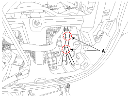
Remove the passenger compartment junction box mounting clips (A).
|
| 28. |
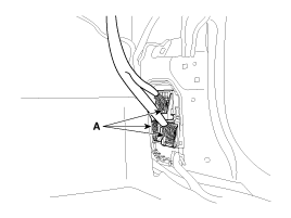
Disconnect the multi box connectors (A).
[Driver's]
[Passenger's]
|
| 29. |
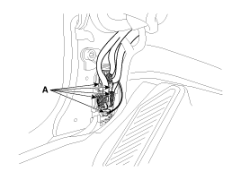
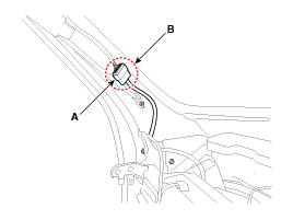
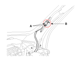
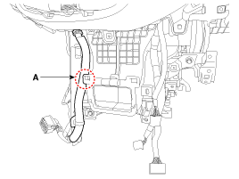
Disconnect the connector (A) and the mounting clips (B) in the
front pillar.
[Driver's]
[Passenger's]
|
| 30. |
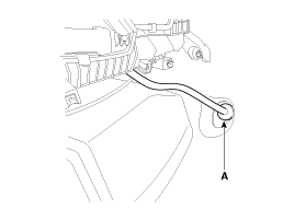
Remove the drain hose (A).
|
| 31. |
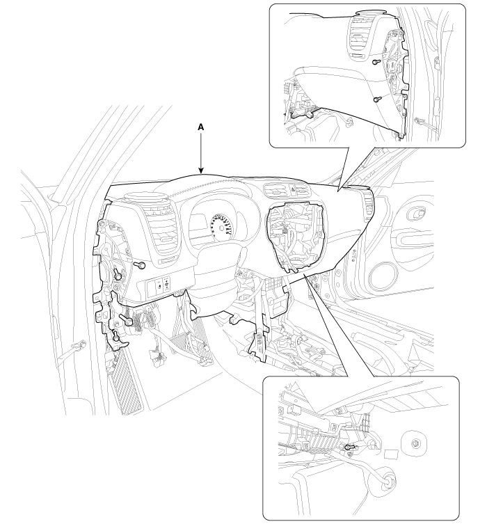
After loosening the bolts remove the main crash pad and cowl cross
bar assembly (A) together.
|
| 32. |
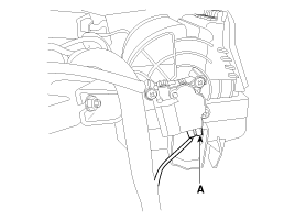
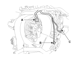
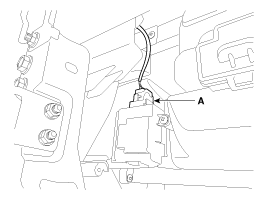
Disconnect the heater & blower unit connectors.
|
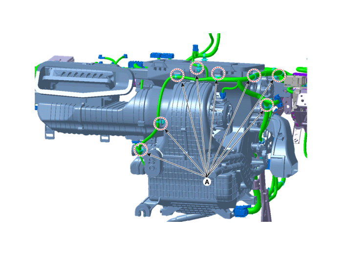
| 33. |
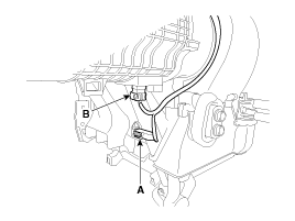
Remove the mounting clips (A).
|
| 34. |
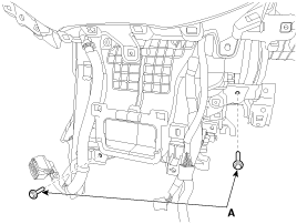
Loosen the heater and blower unit mounting bolts (A)
|
| 35. |
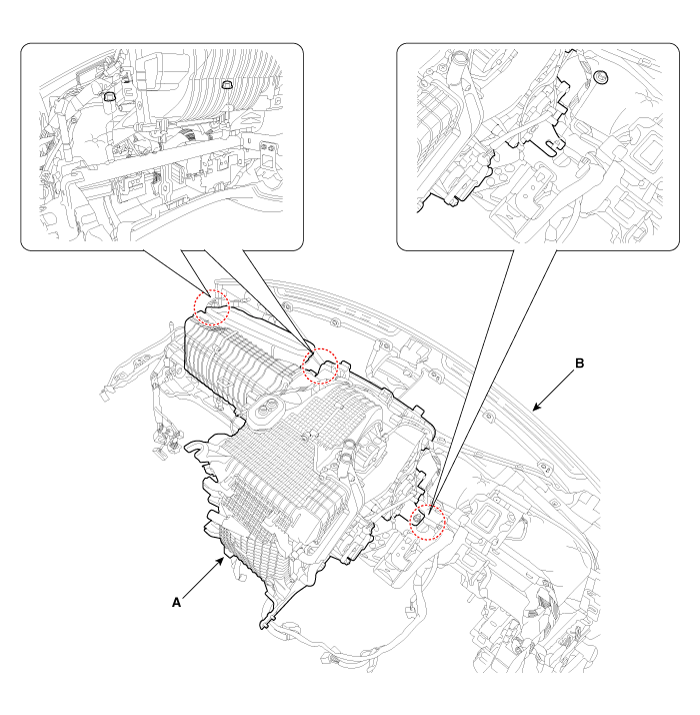
Remove the heater and blower unit (A) from the crash pad (B) after
loosening the mounting nuts.
|
| 36. |
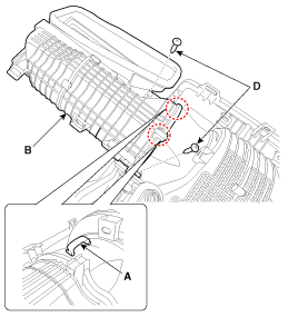
Remove the heater unit mounting clips (A).
|
| 37. |
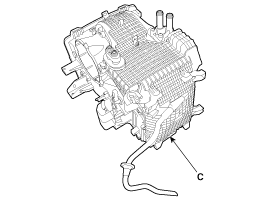
Separate the blower unit (B) from the heater unit (C) after loosening
the screws (D).
|
| 38. |
Install in the reverse order of removal.
|
 Heater Unit Components
[LH]
1. Foot shower left duct
2. Motor&Wheel assembly
3. Mode actuator motor assembly
4. Cam mode
5. Defroster door lever
6. Defroster door ARM
7. Ventila ...
 Heater Core Replacement
1.
Disconnect the negative (-) battery terminal.
2.
Remove the heater and blower assembly.
(Refer to Heater -"Heater Unit")
...
See also:
Rear seat adjustment
Folding the rear seat
The rear seatbacks can be folded to facilitate carrying long items or to increase
the luggage capacity of the vehicle.
WARNING - Folded down seatback
Never allow passengers ...
Components
1. Clutch pedal assembly
2. Ignition lock and clutch switch
3. Master cylinder
4. Clutch tube
...
Side air bag
Your vehicle is equipped with a side air bag in each front seat. The purpose
of the air bag is to provide the vehicle's driver and/or the front passenger with
additional protection than th ...

