 Kia Soul: SRS components and functions
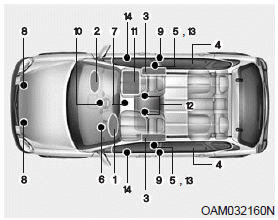
The SRS consists of the following components:
1. Driver's front air bag module
2. Passenger's front air bag module
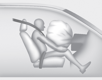
3. Side impact air bag modules
4. Curtain air bag modules
5. Retractor pre-tensioner assemblies
6. Air bag warning light
7. SRS control module (SRSCM)
8. Front impact sensors
9. Side impact sensors
10. PASSENGER AIR BAG “OFF” indicator (Front passenger’s seat only)
11. Occupant detection system (Front passenger’s seat only)
12. Driver’s and front passenger’s seat belt buckle sensors
13. Anchor pretensioner assembly
14. Side pressure sensor
The SRSCM continually monitors all SRS components while the ignition switch is ON to determine if a crash impact is severe enough to require air bag deployment or pre-tensioner seat belt deployment.
The SRS air bag warning light on the instrument panel will illuminate for about 6 seconds after the ignition switch is turned to the ON position, after which the SRS air bag warning light should go out.
If any of the following conditions occurs, this indicates a malfunction of the SRS. Have an authorized Kia dealer inspect the air bag system as soon as possible.
- The light does not turn on briefly when you turn the ignition ON.
- The light stays on after illuminating for approximately 6 seconds.
- The light comes on while the vehicle is in motion.
- The light blinks when the ignition switch is in ON position.
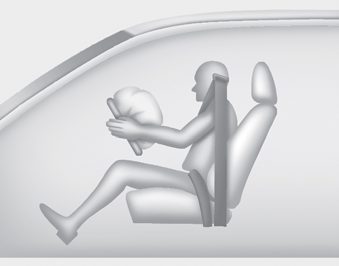
Driver’s front air bag (1)
The front air bag modules are located both in the center of the steering wheel and in the front passenger's panel above the glove box. When the SRSCM detects a sufficiently severe impact to the front of the vehicle, it will automatically deploy the front air bags.
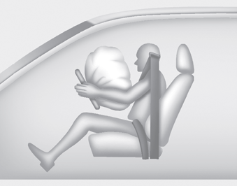
Driver’s front air bag (2)
Upon deployment, tear seams molded directly into the pad covers will separate under pressure from the expansion of the air bags. Further opening of the covers then allows full inflation of the air bags.
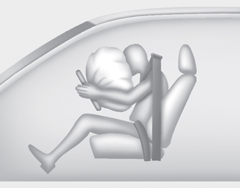
Driver’s front air bag (3)
A fully inflated air bag, in combination with a properly worn seat belt, slows the driver's or the passenger's forward motion, reducing the risk of head and chest injury.
After complete inflation, the air bag immediately starts deflating, enabling the driver to maintain forward visibility and the ability to steer or operate other controls.
Passenger’s front air bag
WARNING - Air bag obstructions
Do not install or place any accessories on the steering wheel, instrument panel, or on the front passenger's panel above the glove box in a vehicle Such objects may become dangerous projectiles if the air bag deploys.
✽ NOTICE
Before you replace a fuse or disconnect a battery terminal, turn the ignition switch to the LOCK position and remove the ignition switch. Never remove or replace the air bag related fuse(s) when the ignition switch is in the ON position. Failure to heed this warning will cause the SRS air bag warning light to illuminate.
 Air bag warning light
The purpose of the air bag warning light in your instrument panel is to alert
you of a potential problem with your air bag - Supplemental Restraint System (SRS).
When the ignition switch is turne ...
 Occupant detection system
Type A
Type B
Your vehicle is equipped with an occupant detection system in the front passenger's
seat.
The occupant detection system is designed to detect the presence of a properly-seat ...
See also:
Gasoline containing alcohol and methanol
Gasohol, a mixture of gasoline and ethanol (also known as grain alcohol), and
gasoline or gasohol containing methanol (also known as wood alcohol) are being marketed
along with or instead of leade ...
Rail Pressure Sensor (RPS). Specifications
Specification
...
Description
The ECM (Electro Chromatic inside rear view Mirror) is intended dim
the reflecting light in the rear view mirror. The forward facing sensor
detects brightness of the surroundings, while th ...