 Kia Soul: Seat Heater Switch Components
Kia Soul 2014-2019 PS Service Manual / Body Electrical System / Seat Electrical / Seat Heater Switch Components
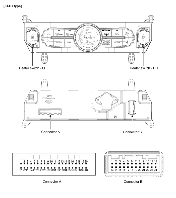
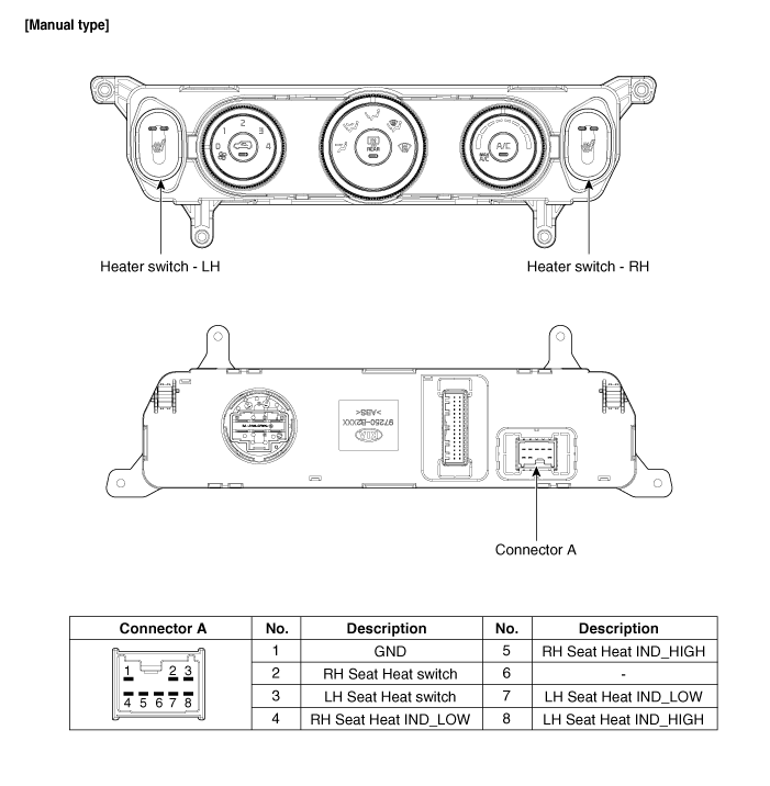
| [First Row Seat] |

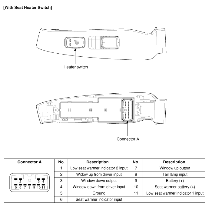
Connector Pin Information
| Connector |
Pin NO |
Function |
Connector |
Pin NO |
Function |
| A |
1 |
ILL(+) |
A |
33 |
ECV (+) |
| 2 |
SENSOR REF (+5) |
34 |
ECV (-) |
||
| 3 |
C_CANHIGH |
35 |
FET (GATE) |
||
| 4 |
C_CAN LOW |
36 |
MM_CAN HIGH |
||
| 5 |
MODE ACT'R (VENT) |
37 |
MM_CAN LOW |
||
| 6 |
MODE ACT'R (DEF) |
38 |
RH SEAT HEAT INDICATOR - LOW |
||
| 7 |
MODE ACT'R F/B |
39 |
RH SEAT HEAT INDICATOR - MID |
||
| 8 |
INTAKE ACT'R (FRE) |
40 |
RH SEAT HEAT INDICATOR - HIGH |
||
| 9 |
INTAKE ACT'R (REC) |
B |
1 |
GND |
|
| 10 |
INTAKE ACT'R F/B |
2 |
SENSOR GND |
||
| 11 |
K-LINE |
3 |
FET (DRAIN F/B) |
||
| 12 |
HTD |
4 |
IONIZER DIAGNOSIS |
||
| 13 |
REAR DEFOG S/W |
5 |
CLEAN SIGNAL |
||
| 14 |
TEMP ACT'R (COOL) |
6 |
ION SIGNAL |
||
| 15 |
TEMP ACT'R (WARM) |
7 |
- |
||
| 16 |
TEMP ACT'R F/B |
8 |
- |
||
| 17 |
LH SEAT HEAT INDICATOR - LOW |
9 |
RH VETILATION SEAT SW |
||
| 18 |
LH SEAT HEAT INDICATOR - MID |
10 |
LH VETILATION SEAT SW |
||
| 19 |
LH SEAT HEAT INDICATOR - HIGH |
11 |
IGN1 |
||
| 20 |
ILL - (RHEO) |
12 |
IGN2 |
||
| 21 |
DETENT OUT (+) |
13 |
GND |
||
| 22 |
LH SEAT HEAT SW |
14 |
- |
||
| 23 |
PTC RLY 2 |
15 |
- |
||
| 24 |
PTC RLY 3 |
16 |
- |
||
| 25 |
PTC ON SIGNAL |
17 |
- |
||
| 26 |
RH SEAT HEAT SW |
18 |
LH VENTILATION SEAT INDICATOR - LOW |
||
| 27 |
AMBIENT SENSOR (+) |
19 |
LH VENTILATION SEAT INDICATOR - MID |
||
| 28 |
EVAP SENSOR (+) |
20 |
LH VENTILATION SEAT INDICATOR - HIGH |
||
| 29 |
RH SEAT COOLER INDICATOR - LOW |
21 |
- |
||
| 30 |
RH SEAT COOLER INDICATOR - MID |
22 |
BLWER MOTOR (+) |
||
| 31 |
RH SEAT COOLER INDICATOR - HIGH |
23 |
ISG DC |
||
| 32 |
PHOTO SENSOR (-) |
24 |
BATTERY |

| Second Row Seat |

 Power Seat Control Switch Installation
1.
Install the power seat control switch after connecting the
connector.
2.
Install the front seat shield outer cover.
...
 Seat Heater Switch Circuit Diagram
[First Row Seat]
Second Row Seat
...
See also:
Special Service Tools
Tool Name / Number
Illustration
Description
Engine support fixture (bar)
09200-3N000
Used for holding engine assembly when removing
/ in ...
Luggage room lamp
The luggage room lamp comes on when the tailgate is opened.
The lamp comes on as long as the tailgate is open. To prevent unnecessary charging
system drain, close the tailgate securely after us ...
Hazard warning flasher
The hazard warning flasher should be used whenever you find it necessary to stop
the vehicle in a hazardous location. When you must make such an emergency stop,
always pull off the road as far a ...
