Inspection
|
1. |
Connect the GDS on the Data Link Connector (DLC).
|
|
2. |
Measure the output voltage of the MAPS at idle and IG ON.
Specification:
Refer to "Specification"
|
|
Removal
|
1. |
Turn the ignition switch OFF and disconnect the battery negative
(-) cable.
|
|
2. |
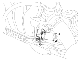
Disconnect the manifold absolute pressure sensor connector (A).
|
|
3. |
Remove the installation bolt (B), and then remove the sensor from
the surge tank.

|
Installation
| •
|
Install the component with the specified torques.
|
| •
|
Note that internal damage may occur when the component
is dropped. If the component has been dropped, inspect before
installing.
|
|
| •
|
Insert the sensor in the installation hole and be careful
not to damage.
|
|
|
1. |
Install in the reverse order of removal.
Manifold absolute pressure sensor
installation bolt:
9.8 ~ 11.8 N.m (1.0 ~ 1.2 kgf.m, 7.2 ~ 8.7 lb-ft)
|
|
Circuit Diagram
(M/T)
(A/T)
...
Description
Intake Air Temperature Sensor (IATS) is included inside Manifold Absolute
Pressure Sensor and detects the intake air temperature.
To calculate precise air quantity, correction o ...
See also:
Multi box
To open the box, pull the lever and the cover will open.
Push down the cover to close. ...
System operation
Ventilation
1. Set the mode to the
position.
2. Set the air intake control to the outside (fresh) air position.
3. Set the temperature control to the desired position.
4. Set the fan speed con ...
2. TCM Terminal Function
Connector [A]
Pin
Description
Pin
Description
22
Overdrive clutch control solenoid valve (ODC_VFS)
73
Inhibitor switch signal "S4 ...
 Kia Soul: Manifold Absolute Pressure Sensor (MAPS). Repair procedures
 Manifold Absolute Pressure Sensor (MAPS). Schematic Diagrams
 Intake Air Temperature Sensor (IATS). Description and Operation

