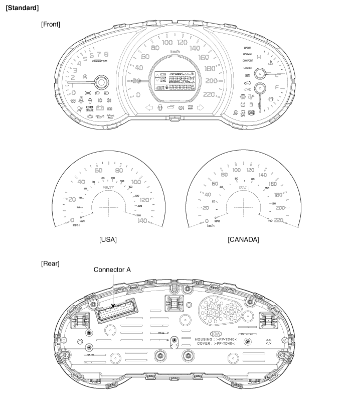
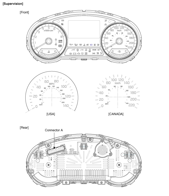
 Kia Soul: Instrument Cluster Components
Kia Soul 2014-2019 PS Service Manual / Body Electrical System / Indicators And Gauges / Instrument Cluster Components


Connector Pin Information
| No. |
Description |
No. |
Description |
| 1 |
Ground signal 3 |
21 |
Trip switch (-) input |
| 2 |
Illumination output (-) |
22 |
Trip switch 1 (+) input (Trip button) |
| 3 |
Rheostat switch down input |
23 |
Trip switch 2 (+) input (Cruise button) |
| 4 |
Rheostat switch up input |
24 |
Speed input (-) |
| 5 |
Detent output (+) |
25 |
- |
| 6 |
P output (+) (A/T) |
26 |
Low washer level input (-) |
| 7 |
R output (+) (A/T) |
27 |
Oil pressure switch input (-) |
| 8 |
N output (+) (A/T) |
28 |
- |
| 9 |
D output (+) (A/T) |
29 |
- |
| 10 |
S output (+) (A/T) |
30 |
- |
| 11 |
ALT L output |
31 |
- |
| 12 |
ALT L input (-) (Battery charge) |
32 |
C CAN high |
| 13 |
- |
33 |
C CAN low |
| 14 |
Fuel sender (+) input |
34 |
- |
| 15 |
Airbag (+) input |
35 |
- |
| 16 |
Fuel sender (-) input |
36 |
Active ECO switch input |
| 17 |
Immobilizer input |
37 |
Ground signal 1 |
| 18 |
Speed output (4P output) |
38 |
R input (M/T) |
| 19 |
LDC(Battery (+)) input |
39 |
Ignition 1 |
| 20 |
Tail lamp input (Illumination (+)) |
40 |
Battery (+) |


Connector Pin Information
| No. |
Description |
No. |
Description |
| 1 |
Ground signal 3 |
21 |
Trip switch (-) input |
| 2 |
Illumination output (-) |
22 |
Trip switch 1 (+) input (Trip button) |
| 3 |
Rheostat switch down input |
23 |
Trip switch 2 (+) input (Cruise button) |
| 4 |
Rheostat switch up input |
24 |
Speed input (-) |
| 5 |
Detent output (+) |
25 |
- |
| 6 |
P output (+) (A/T) |
26 |
Low washer level input (-) |
| 7 |
R output (+) (A/T) |
27 |
Oil pressure switch input (-) |
| 8 |
N output (+) (A/T) |
28 |
Heated wheel indicator input |
| 9 |
D output (+) (A/T) |
29 |
M CAN low |
| 10 |
S output (+) (A/T) |
30 |
M CAN high |
| 11 |
ALT L output |
31 |
- |
| 12 |
ALT L input (-) (Battery charge) |
32 |
C CAN high |
| 13 |
- |
33 |
C CAN low |
| 14 |
Fuel sender (+) input |
34 |
- |
| 15 |
Airbag (+) input |
35 |
- |
| 16 |
Fuel sender (-) input |
36 |
Active ECO switch input |
| 17 |
Immobilizer input |
37 |
Ground signal 1 |
| 18 |
Speed output (4P output) |
38 |
R input (M/T) |
| 19 |
LDC(Battery (+)) input |
39 |
Ignition 1 |
| 20 |
Tail lamp input (Illumination (+)) |
40 |
Battery (+) |
 Component Location
1. Cluster assembly
2. Seat belt switch
3. Vehicle speed sensor
4. Engine coolant temperature sender
5. Oil pressure switch
6. Brake fluid level warning switch ...
See also:
Evaporator Temperature Sensor Description
The evaporator temperature sensor will detect the evaporator core temperature
and interrupt compressor relay power in order to prevent evaporator from freezing
by excessive cooling
...
Carry emergency equipment
Depending on the severity of the weather, you should carry appropriate emergency
equipment. Some of the items you may want to carry include tow straps or chains,
flashlight, emergency flares, sand ...
Brake lines, hoses and connections Inspection
Visually check for proper installation, chafing, cracks, deterioration
and any leakage
Replace any deteriorated or damaged parts immediately. ...

